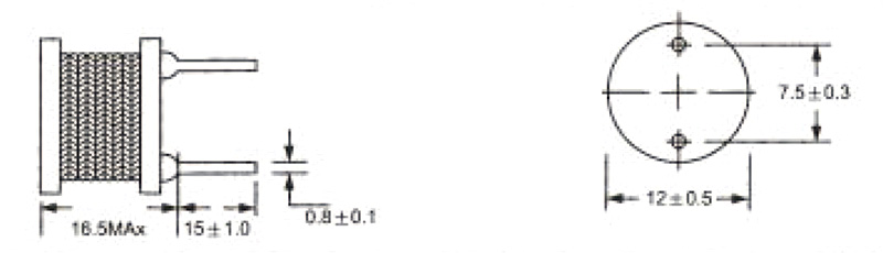
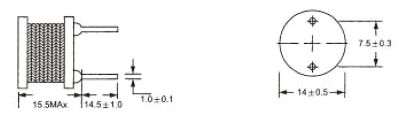
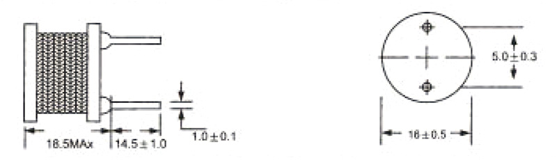
Product

DIP Power Inductor
Leaded Power Inductor

GDR TYPE

Leaded Power Inductor

Features
We are professional manufacturer of Inductor, providing Leaded Power Inductor and Power Inductor.

  • The GDR series power inductor have low DC resistance and large permissible DC current with high reliability.
  • Magnetic shielded products are available for each series for the consideration against radiation.
  • The GDR series has high saturation magnetic-flux density and high efficiency
  • Open Magnetic circuit construction .Low cost and high reliability
View More Details
Description
Product Identification
GDR
1
0608
2
1R0
3
K
4
U
5
  1. PRODUCT TYPE CODE
  2. CORE DIMENSION
  3. INDUCTANCE CODE
  4. INDUCTANCE TOLERANCE (K:±10%,M:±20%,N:±30%)
  5. UL TUBE
Product Series
Type Dimensions (mm)
GDR-0406 (1μH~1.0μH)
GDR-0608 (1μH~1.0μH)
GDR-0810 (100μH~1.0μH)
GDR-0912 (100μH~1.0μH)
GDR-1216 (10μH~1.0μH)
GDR-1415 (10μH~1.0μH)
GDR-1618 (10μH~1.0μH)
Specification
Part No. Inductance
L(μH)
Test Frequency DC Resistance(Ω) Max.
0406 0608 0810 0912 1216 1415 1618
1R0 1.0   0.021 0.024          
1R2 1.2   0.030 0.027          
1R5 1.5   0.034 0.030          
1R8 1.8   0.037 0.032          
2R2 2.2   0.040 0.035          
2R7 2.7   0.045 0.042          
3R3 3.3 7.96MHz 0.058 0.049          
3R9 3.9   0.066 0.056          
4R7 4.7   0.072 0.061          
5R6 5.6   0.081 0.089          
6R8 6.8   0.087 0.092          
8R2 8.2   0.108 0.100          
100 10   0.124 0.13     0.015 0.017  
120 12   0.160 0.16          
150 15   0.187 0.19     0.020 0.021  
180 18   0.219 0.25     0.022    
220 22   0.295 0.30     0.025 0.026 0.031
270 27   0.330 0.40     0.027 0.028 0.035
330 33 2.52MHz 0.375 0.55     0.030 0.031 0.037
390 39   0.460 0.59     0.032 0.035 0.052
470 47   0.540 0.61     0.035 0.046 0.056
560 56   0.664 0.63     0.040 0.051 0.058
680 68   0.819 0.65     0.055 0.055 0.062
820 82   1.431 0.68     0.060 0.058 0.076
101 100   0.105 0.74 0.26 0.135 0.086 0.075 0.108
121 120   1.515 0.76 0.31 0.175 0.093 0.100 0.132
151 150   1.770 0.80 0.38 0.200 0.100 0.125 0.152
181 180   1.725 0.85 0.44 0.227 0.115 0.141 0.163
221 220   1.753 0.89 0.50 0.316 0.145 0.208 0.216
271 270   3.036 1.01 0.60 0.366 0.166 0.240 0.053
331 330 1KHz 3.432 1.08 0.78 0.467 0.190 0.272 0.270
391 390   3.864 1.32 0.85 0.532 0.241 0.303 0.341
471 470   4.368 1.45 1.08 0.656 0.311 0.342 0.390
561 560   5.664 1.60 1.19 0.741 0.352 0.531 0.425
681 680   6.480 1.85 1.59 0.917 0.405 0.590 0.565
821 820   7.296 2.00 1.88 1.195 0.530 0.728 0.700
102 1000   10.20 2.30 2.30 1.362 0.606 0.750 0.881
Tolerance of inductance:1.0~82μH±20%(M) 1000~10,000μH=±10%(K)
The rated current indicates he value of current when the inductance is 10% lower than is initial value at DC superposition or DC current when 40℃, whichever is lower
Part No. Inductance
L(μH)
Test Frequency Permissible DC Current(A) Max.
0406 0608 0810 0912 1216 1415 1618
1R0 1.0   4.5 2.10          
1R2 1.2   4.0 2.05          
1R5 1.5   3.6 2.00          
1R8 1.8   3.3 1.95          
2R2 2.2   3.0 1.90          
2R7 2.7   2.7 1.85          
3R3 3.3 7.96MHz 2.5 1.80          
3R9 3.9   2.3 1.75          
4R7 4.7   2.2 1.70          
5R6 5.6   2.0 1.65          
6R8 6.8   1.8 1.60          
8R2 8.2   1.6 1.55          
100 10   1.5 1.50     4.2 14  
120 12   1.3 1.35          
150 15   1.2 1.30     3.3 10  
180 18   1.1 1.25     3.3    
220 22   1.0 1.15     3.0 8.8 14.0
270 27   0.9 1.10     2.5 8.3 13.5
330 33 2.52MHz 0.85 1.05     2.3 7.8 13.0
390 39   0.80 1.00     2.1 7.3 12.5
470 47   0.70 0.95     2.0 6.7 11.5
560 56   0.60 0.90     1.8 6.2 11.0
680 68   0.55 0.83     1.7 5.7 9.2
820 82   0.50 0.78     1.6 5.2 8.7
101 100   0.46 0.70 1.4 1.70 1.4 4.6 7.7
121 120   0.41 0.62 1.3 1.50 1.2 4.2 7.0
151 150   0.37 0.57 1.1 1.40 1.0 3.7 6.5
181 180   0.35 0.53 1.0 1.30 0.9 3.5 6.0
221 220   0.32 0.49 0.9 1.10 0.90 3.0 5.5
271 270   0.28 0.45 0.83 1.00 0.79 2.7 5.0
331 330 1KHz 0.25 0.41 0.78 0.93 0.74 2.5 4.4
391 390   0.23 0.37 0.70 0.86 0.69 2.3 3.9
471 470   0.20 0.32 0.63 0.87 0.58 2.1 3.6
561 560   0.20 0.29 0.60 0.71 0.54 1.8 3.3
681 680   0.18 0.26 0.55 0.65 0.52 1.7 2.9
821 820   0.16 0.22 0.50 0.59 0.47 1.5 2.7
102 1000   0.14 0.20 0.45 0.53 0.45 1.4 2.5
Tolerance of inductance:1.0~82μH±20%(M) 1000~10,000μH=±10%(K)
The rated current indicates he value of current when the inductance is 10% lower than is initial value at DC superposition or DC current when 40℃, whichever is lower
Applications
  • For the smoothing circuit of DC-DC converter, as a choke coil or chopper coil.
  • Suitable for use in power lines of camcorder, LCD set, OA equipment, notebook computer, PDA, and small size communication equipment.
  • Notebook; Inkjet printer; Copying machine; ADSL modem; Cellular phone; Display monitor
OEM/ODM
G-CHEN will also produce devices outside these specifications to meet specific customer requirements, please contact our sales for more information.
Loading...